Managing Receive Connectors
Exchange Server 2003 uses the SMTP Virtual Server that comes with the Operation System to control message flow. In Exchange Server 2007 the SMTP service bits are installed within the Exchange Server 2007 installation process. Because of this, we have two different components when we are talking about SMTP traffic in the Exchange 2007 architecture: the receive connectors and the send connectors. They are configured in two different places, the Send Connector is configured at Organization level and the receive connector at Server level. The receive connector is responsible for all SMTP incoming traffic which can originate from an external source, a client, a partner, or another Exchange Server and on top of that the receive connector uses authentication and some other features to manage all received connections.
By default Exchange Server 2007 has two new receive Connectors called Client Receive Connector and Default <Server Name>, where <Server Name> is the Netbios name of the Exchange Server. The default Receive connectors can be found under Server Configuration / Hub item using the Exchange Management Console, as shown in Figure 01. They can also be found using the Get-ReceiveConnector cmdlet through the Exchange Management Shell. By default any new Exchange Server can receive messages from other Hub Transport servers due the Default Receive connector which is named Default <Server Name> and is configured to receive traffic from any host, to any local IP address on port 25 but this traffic must be authenticated first.


Figure 01
Creating a Receive connector
Now we are going to create a new Receive Connector from scratch and during the process we will explain the available options that can be defined during the wizard. The server used in this article has two IP addresses: 172.16.171.11 and 172.16.171.12.
Each connector has a unique set of the following attributes: IP Address, Port number and remote IP Address range. These parameters are always validated during the New Receive Connector wizard. If you have an existent connector with the same values a new connector cannot be created.
In this article we are going to create an Internet Receive Connector using the second IP address of the server, as follows:
- Open the Exchange Management Console.
- Expand Server Configuration.
- Click on Hub Transport.
- Select the server name on the right hand side.
- In the Toolbox Actions. Click on New Receive Connector.
- Introduction. Let’s name this new connector using the Name field, and we can also select which kind of connector it is for (Figure 02). We have five options: Internet, Internal, Partner, Client and Custom and each one of them defines a set of authentication and permissions on the connector that we are creating. The choice of connector also changes the New Receive Connector wizard, so it is not the same wizard for all types of pre-configured connectors. In this article we are going to start playing with an Internet Receive Connector, so let’s click on Internet and click on Next.
Note:
If we choose a wrong type of connector we can always change the configuration afterwards. It is not necessary to recreate it due to choosing the incorrect option.

Figure 02
Okay, what if we had chosen Client, Partner or Internal instead of Internet? What would be the difference? The following table shows which changes will be applied for each type of receive connector chosen. We have three columns, the first one (During Wizard) shows which information will be required during the New Receive Connector Wizard; the second one (Authentication) shows what authentication method will be configured by default in the new Receive Connector and the last one (Permissions) shows which groups are marked in the Receive Connector permissions. Remember that all those values can be changed through the Exchange Management Console or Exchange Management Shell afterwards.
During Wizard
|
Authentication
|
Permissions
| |
Internet
|
In Local Network settings page, we can manage the Local IP Address(es), Port and specify FQND.
|
TLS
|
Anonymous Users
|
Internal
|
In Remote network settings we can change the remove IP Address range.
|
TLS
Exchange Server Authentication
|
Exchange Servers,
Legacy Exchange Servers
|
Client
|
In Remote network settings we can change the remove IP Address range.
|
TLS
Basic Authentication and Offer Basic authentication only after starting TLS
|
Exchange Users
|
Partner
|
On the Local Network settings page we can manage the Local IP Address(es), Port and specify FQND.
In Remote network settings we can change the remove IP Address range.
|
TLS and Enable Domain Security (Mutual Auth TLS)
|
Partners
|
Custom
|
On the Local Network settings page we can manage the Local IP Address(es), Port and specify FQND.
In Remote network settings we can change the remove IP Address range.
|
TLS
|
None
|
We will go over Authentication and Permissions later on in this article series, for now let’s finish our Internet Receive Connector.
- Local Network Settings. Let’s use only the second IP address of the local server on port 25. We are also going to use the mail.andersonpatricio.org as FQDN, as shown in Figure 03. This name will be displayed when a connection is established with this Receive Connector. Click on Next.

Figure 03
- New Connector. A summary of our choices made so far. Click on New to create the Receive Connector.
- Completion. Final screen of the new receive connector wizard with all the information provided during the wizard and the cmdlet used to create it. Click on Finish.
Okay, these are the steps required to create a new receive connector; we can do the same using the Exchange Management Shell. To create we have to use the New-ReceiveConnector cmdlet. In this example we are going to create the same connector described in the steps above:
New-ReceiveConnector -Name “Connector Name” –Usage:Internet –Bindings:<Specific IP Address or 0.0.0.0 for all IP addresses>:<port number> -fqdn: ‘<FQDN that will be used by this connector>’ –Server <Hub transport Server name>
Testing the new Receive connector…
Okay, we have just created our new connector. We can start testing it using the following command: telnet 172.16.171.12 25 where 25 is the port that will be used (Figure 04). The connection will be made and the FQDN name that we defined in our new Receive Connector will be shown. If we try to connect using the IP address 172.16.171.11 we will receive a different prompt because it is a different connector. Our Internet connector is only listening on the 172.16.171.12 IP address.


Figure 04
Load Balancing Exchange 2007 SP1 Hub Transport Servers using Windows Network Load Balancing
Exchange Server 2007 (RTM and SP1) Hub Transport servers are resilient by default. This means that if you install more than one Hub Transport server in an Active Directory (AD) site and one fails, the other(s) will continue to accept connections. In addition, when you have more than one Hub Transport server deployed in an AD site, connections will be load balanced automatically between the Hub Transport servers. There is only one exception to this rule, and that is when a Hub Transport server role is installed on a server also holding the Mailbox server role. In this specific scenario the Hub Transport server local to the Mailbox server will always be preferred over other Hub Transport servers in the AD site.
The resilient behaviour that by default is built into the Hub Transport server works just fine for many organizations, but there are situations where you as an Exchange messaging administrator or consultant, for example, have a line of business (LOB) application, Microsoft Office SharePoint Server 2007 (MOSS 2007) portal, or perhaps a System Center Operations Manager 2007 (SCOM 2007) service management solution which, in order to submit messages to an Exchange organization must use a SMTP relay as these applications cannot log on to a mailbox using MAPI and then send the messages as that mailbox.
So what are your options in these types of scenarios? Well, with the Exchange Server 2007 RTM version, it was not supported to load-balance Hub Transport servers using Windows Network Load Balancing (WNLB) technology. This meant that if you had an application which needed to use your Exchange 2007 messaging environment to relay messages, you either had to specify two SMTP servers in the application (often not possible), use DNS round robin (not as intelligent as NLB) or MX records (not viable if the application only allows you to specify a smart host).
As mentioned load balancing Hub Transport servers in Exchange 2007 RTM was not a supported scenario, but now that Exchange Server 2007 Service Pack 1 (SP1) has been released guess what? Yes you’re right, it’s supported to load balance Hub Transport servers using a hardware load balancer or standard WNLB technology.
Although it’s now supported to configure Hub Transport servers in an NLB, please note that it isn’t supported to load balance connections between Hub Transport servers on your internal corporate production network using this method. You should only use NLB to load balance inbound SMTP connections from applications (such as LOB application, MOSS, and SCOM 2007 etc.) and other non-Exchange sources as well as client connections (in order to send messages, POP & IMAP clients uses the default client receive connector on a Hub Transport server).
Although it’s now supported to configure Hub Transport servers in an NLB, please note that it isn’t supported to load balance connections between Hub Transport servers on your internal corporate production network using this method. You should only use NLB to load balance inbound SMTP connections from applications (such as LOB application, MOSS, and SCOM 2007 etc.) and other non-Exchange sources as well as client connections (in order to send messages, POP & IMAP clients uses the default client receive connector on a Hub Transport server).
In this article series, I’ll show you step by step how you configure Hub Transport servers in a NLB using WNLB. We’ll also verify things works as expected as well as take a look at how fault tolerance and load balancing works for outbound message flow (messages leaving the Exchange organization).
Environment used in this article
If you want to deploy and test the solution explained in this article series in your own environment (you should of course always start out in your lab environment), you will need the following:
- 1 x Windows 2003 Server SP2 Domain Controller and Global Catalog (DC01)
- 1 x Windows 2003 Server SP2 with Exchange 2007 SP1 Mailbox and Client Access Server role installed (Mailbox01)
- 2 x Windows 2003 Server SP2 with Exchange 2007 SP1 Hub Transport Server role installed (HT01 & HT02)
Note:
Because the NLB cluster configured in this article series is configured in unicast mode, you need to install two network interface cards (NICs) in each Hub Transport server.
Because the NLB cluster configured in this article series is configured in unicast mode, you need to install two network interface cards (NICs) in each Hub Transport server.
Creating the Alias (FQDN) for the NLB Cluster in DNS
With the environment up and running the very first thing you want to do is to create an A-record for the NLB cluster name in DNS. To do so log on to the domain controller in your Active Directory forest, then open the DNS manager by clicking Start > Run and type dnsmgmt.msc.
Now expand the Forward Lookup Zones container and right-click on the respective forward lookup zone for your Active Directory. On the context menu select New Host (A), then type the name you want to use. As you can see in Figure 1.1, I used MAIL for the purpose of this setup. Then type the IP address you want to use as the Windows NLB cluster IP address (this should be an IP address on the same subnet as the NLB member servers).


Figure 1.1: Creating a DNS Record for the Windows NLB Cluster name in the DNS Manager
Now click Add Host (Figure 1.2) then OK and Done. Close the DNS Manager.


Figure 1.2: Entering the DNS name and IP address
Configuring Network Settings for each NLB Cluster Node
Although not required (as explained earlier), we will use unicast mode with two network adapters installed in this setup (this gives us the most optimal performance). To configure the second network adapter on each Exchange 2007 Hub Transport server, open Network Connections and give each LAN connection a meaningful name as shown in Figure 1.3.


Figure 1.3: Naming the Network Connections
Now open the Property page for the NLB adapter and then configure the TCP/IP settings as shown in Figure 1.4. As you can see you should only specify an IP address and a Subnet mask. When ready click OK.


Figure 1.4: Configuring the TCP/IP Settings for the NLB NIC
Enabling Network Load Balancing on the First Hub Transport Server
Okay, it’s time to enable NLB on the first Hub Transport server in our setup. This can be done via the property page of the network adapter, or by using the Network Load Balancing Manager. I will enable it via the property page of the network adapter, and then add the second Hub Transport server to the NLB cluster in the next section. So let us open the property page of the NLB LAN adapter, and then check Network Load Balancing as shown in Figure 1.5. With Network Load Balancing selected click the Properties button.


Figure 1.5: Enabling Network Load Balancing
Under the Cluster Parameters tab (Figure 1.6) enter the IP address, subnet mask and full Internet name for the NLB cluster. Next make sure unicast is selected under Cluster operation mode.


Figure 1.6: Configuring the Cluster Parameters
Now, click the Host Parameters tab and enter the IP address and subnet mask configured for the network adapter (Figure 1.7). Let the other settings stay at their defaults.


Figure 1.7: Configuring the Host Parameters
Click the Port Rules tab then select the default port rule and click Remove.
We now need to add a port rule for each of the ports the NLB cluster should accept client requests on. To do so click the Add button, then enter the respective port under Port range (Figure 1.8). Also make sure Affinity is set to Single. Finally click OK to add the port rule.


Figure 1.8: Configuring the NLB Cluster Port Rules
Do this for each required port, so you get a list of rules similar to what is shown in Figure 1.9 depending on what client access services you want to allow in your organization.


Figure 1.9: List of Configured Port Rules
Click OK and OK again to the Information message you receive (Figure 1.10).


Figure 1.10: Informational dialog box
Now add the new virtual cluster IP address under the TCP/IP property page of the network adapter as shown in Figure 1.11.


Figure 1.11: Adding the NLB Cluster IP Address on the TCP/IP Settings Page
Finally click Add then OK. We have now setup a Windows NLB cluster with one member server.
Adding the Second Hub Transport Server to the NLB Cluster
What good is a NLB cluster with only one member server? Correct not very good. So let’s add the second Exchange 2007 Hub Transport server to the cluster as well. To do so open the Network Load Balancing Manager by clicking Start > Run and typing NLBMGR.EXE (or click Administrative Tools > Network Load Balancing Manager). This will open the Network Load Balancing Manager shown in Figure 1.12.


Figure 1.12: Network Load Balancing Manager
To add the second server to the NLB cluster, click Cluster in the menu, then Add Host. In the appearing window, type the name of the second Hub Transport server then hit Connect (Figure 1.13). Select the respective cluster and click Finish.


Figure 1.13: Adding the Second Hub Transport Server to the NLB Cluster
Next, type the IP address and subnet mask of the network adapter that should be associated with the NLB cluster then click Finish (Figure 1.14).


Figure 1.14: Configuring the Host Parameter Settings for the Second Hub Transport Server
Now wait for a little while in order for the server to be added and configured accordingly (Figure 1.15).


Figure 1.15: Second Hub Transport Server added to the NLB Cluster
Close the Network Load Balancing Manager. We have now load-balanced the Hub Transport servers in our lab environment, but there are still a couple of configuration steps to do.
That was all I had to share with you this time, but you can look forward to the second article in this articles series, which will be released in a near future. Until then have a nice one!
Creating an addition receive connector on the Hub Transport servers
As mentioned back in part 1 of this article series, it’s only supported to load balance inbound SMTP connections coming from applications (such as LOB application, MOSS 2007, SCOM 2007 etc.) and other non-Exchange sources using WNLB technology. In order to not affect intra-org communication (aka Hub Transport server to Hub Transport server communication), we must create a new receive connector that listen on port 25/SMTP using the virtual IP address we specified when we created the NLB cluster. To do so launch the Exchange Management Console and then click Server Configuration followed by Hub Transport. Now select the first Hub Transport server in the result pane and then open the property page for the default <server> receive connector in the work pane as shown in Figure 2.1 below.


Figure 2.1: Opening the property page for the default <server> receive connector
Click the Network tab and configure the IP address to the internal non-cluster IP address (Figure 2.2).


Figure 2.2: Specifying a non-clustered IP address for the default <server> receive connector
Now create a new receive connector (type Custom) and name it Inbound SMTP relay (WNLB), then click Next (Figure 2.3).


Figure 2.3: Naming the new Receive WNLB receive connector
On the Local Network Settings page (Figure 2.4), configure the receive connector, so it only listens on port 25 on the NLB cluster address, which in the example is 10.10.1.194. Although optional, it’s also a good idea to enter a FQDN for the connector. Click Next.


Figure 2.4: Configuring the receive connector to listen on the virtual NLB cluster IP address
Now enter the IP addresses that should be allowed to relay through the receive connector. Make sure not to specify a ranger here, but only the specific IP addresses configured on the servers running the applications that must submit messages to the Exchange 2007 organization via this receive connector (Figure 2.5). Then click Next.


Figure 2.5: IP address that should be allowed to submit messages to this receive connector
Finally click New and then Finish to create the new receive connector (Figure 2.6).


Figure 2.6: Completion page
Now open the property page for the new receive connector, and then click the Permission Groups tab. Under the Permission Groups tab, tick Anonymous users and nothing else as shown in Figure 2.7.


Figure 2.7: Allowing anonymous users to submit message to the receive connector
Next we must grant the permissions required in order for the specified remote IP addresses to be able to relay through this receive connector. To do so, open the Exchange Management Shell and type the following command:
Get-ReceiveConnector "Inbound SMTP relay (WNLB)" | Add-ADPermission -User "NT AUTHORITY\ANONYMOUS LOGON" -ExtendedRights "ms-Exch-SMTP-Accept-Any-Recipient"


Figure 2.8: Granting the necessary permissions to the new receive connector
Now perform the exact same steps on the second Hub Transport server.
Testing Hub Transport Server Connectivity via NLB Cluster FQDN
Now that the two Hub Transport Servers has been added as nodes in our WNLB cluster as well as new receive connectors have been created specifically for the WNLB virtual IP address, we should be able to telnet to port 25 and 587 using the NLB cluster FQDN, which for the purpose of this article is mail.ehlo.dk. To do so open a command prompt window on a remote server (the server that should be able to submit messages to the Exchange 2007 organization using the NLB FQDN) and type:
Telnet mail.ehlo.dk 25
You should now get the ESMTP banner from one of the Hub Transport servers as shown in Figure 2.9 below.


Figure 2.9: ESMTP Banner from HT01’s WNLB dedicated receive connector
Telnetting to port 587 should result in similar ESMTP banner (port 587 is the port used by the Client <server> Receive connector in a default Exchange 2007 Hub Transport server).
Let’s also try to telnet the Hub Transport servers using the default <server> receive connector by using the FQDN of the servers themselves (in this case ht01.ehlo.dk and ht02.ehlo.dk). This should result in a slightly different ESMTP banner as shown in Figure 2.10.


Figure 2.10: Telenetting to the default <server> receive connector
So far so good, we have now verified we can submit messages using the new receive connector using the NLB cluster FQDN (mail.ehlo.dk).
Testing Hub Transport Server NLB-based Resiliency
Let’s now see whether the remote server (non-Exchange sources such as a LOB application, MOSS 2007, or SCOM 2007) that needs to submit messages to the Exchange 2007 organization in fact can do so, when one of the nodes in the NLB cluster is down. In order to test this works, let’s drainstop the first node, which in this article is HT01. We do this by opening the NLB Manager and right-clicking on the first node where we select Drainstop in the context menu as shown in Figure 2.11.


Figure 2.11: Drainstopping the first node in the NLB Cluster
When the node is fully drainstopped, the icon will turn red (Figure 2.12) and we can perform our testing.
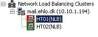
Figure 2.12: HT01 is drainstopped
Let’s try to telnet to port 25 using the NLB cluster FQDN again. As you can see in Figure 2.13, we’re now connected to HT02, which is the second node in our NLB cluster.


Figure 2.13: Telnetting NLB Cluster FQDN result in an ESMTP connection to mail.ehlo.dk
Alright we have now verified, we have a fully working resilient Hub Transport server setup configured using WNLB technology both when speaking intra.org communication as well as communication from non-Exchange sources to the Hub Transport servers. Although it’s outside the scope of this article, you can of course also use a hardware based load balancing solution or if you have multiple ISA Servers configured in an ISA Server array, perform the load balancing on the ISA Servers in your organizations perimeter network.
Providing Fault Tolerance and Load Balancing for Outbound Messages
Now that we have covered how you can provide resiliency for messages submitted from a LOB application using WNLB, I thought it would be a good idea to move on and explain how you load balance as well as provide fault tolerance for outbound mail flow (that is messages leaving the Exchange organization). Actually this is very easily accomplished. You just have to make sure you add more than one Hub Transport server under the Source Server tab of the Send Connector which routes messages on to the Internet (or perhaps to a set of SMTP gateways in your perimeter network). However, bear in mind that load balancing doesn’t work for the particular Send connector unless the Hub Transport servers under the Source Server tab are all from the same Active Directory site.
So in order to add additional Hub Transport source servers to your Send Connector, you need to open the Exchange Management Console (EMC), and then expand the Organization Configuration work center node in the navigation tree in the left side of the EMC. Here you should select Hub Transport and then click the Send Connector tab. Now open the property page for the respective Send Connector, and then click the Source Server tab as shown in Figure 2.14 below. Next, add the required Hub Transport servers by clicking the Add button and apply the settings.


Figure 2.14: Multiple Source Servers on the Internet Send Connector
All outbound messages will now be load balanced between the source servers and if one is down for maintenance etc. the Hub Transport server that needs to deliver messages to recipients outside of the organization will select the next source server in a round robin fashion. There’s one thing you should be aware of though, and that is that if the Hub Transport server that are relaying messages to the Internet also is listed under the Source Server tab of the Send Connector, load balancing will not occur as the local servers proximity always takes precedence overactive directory site proximity.
If the Send Connector that routes messages out of your organization is configured to deliver the messages to a smart host, please be sure to add multiple smart hosts, so that you eliminate all single point of failures in your outbound message routing topology.
If you were using subscribed Edge Transport servers as the anti-spam and/or anti-virus filtering solution in your perimeter network, you would instead of Hub Transport servers add the subscribed Edge Transport servers under the Source Server tab as shown in Figure 2.15. This makes sure that all outbound messages are load balanced between the Edge Transport servers in the perimeter network.

Figure 2.15: Subscribed Edge Transport Server listed under the Source Server tab
Note that only one Edge Transport server is listed in Figure 21, this is simply because I only have one Edge Transport server subscribed to the Exchange organization in the lab environment used for the purpose of this articles series. When using subscribed Edge Transport servers in your Exchange organization, the Send connector settings will automatically be propagated to the Edge Transport servers listed under the Source Server tab.
Testing Fault Tolerance and Load Balancing for Outbound Messages
Okay, let’s verify that the fault tolerance and load balancing mechanisms works as expected. We’ll do so by sending a test message from the 3rd Exchange 2007 server in our lab environment. This server has the Mailbox, Client Access and Hub Transport server roles installed, and although this server is a Hub Transport server it’s not added as source server on the Send Connector, which means that it should deliver the outbound test message to either HT01 or HT02. Figure 2.16 shows the Internet Mail header of the test message in the external recipient’s Mail client.


Figure 2.16: HT01.ehlo.dk is the source server in the Internet Mail Header
Okay it’s now time to turn off the first Hub Transport server (HT01) and then send one more test message, so that we can see HT02 actually takes over. As you can see in Figure 2.17 it does, so our tests were successful.


Figure 2.17: HT02.ehlo.dk is the source server in the Internet Mail Header
A correctly formatted .eml message file that is copied into the Pickup directory is processed for submission in the following steps:
- The Pickup directory is checked for new message files every 5 seconds. You can't modify this polling interval. You can adjust the rate of message file processing by using the PickupDirectoryMaxMessagesPerMinute parameter on the Set-TransportServer cmdlet. The default value is 100 messages per minute. Files that cannot be opened are left in the Pickup directory and are reevaluated at the next poll.
- Limits that are put on message files in the Pickup directory, such as the maximum header size and the maximum number of recipients, are checked. By default, the maximum header size is 64 KB, and the maximum number of recipients is 100 recipients. You change these limits by using the Set-TransportServer cmdlet.
- The file is renamed from <filename>.eml to <filename>.tmp. If the <filename>.tmp file already exists, the file is renamed as <filename><datetime>.tmp. If the file renaming fails, an event log error is generated, and the pickup process proceeds to the next file.
- After the .tmp file is successfully converted into an e-mail message, a "delete on close" command is issued to the .tmp file. The .tmp file appears to remain in the Pickup directory, but the file cannot be opened by anyone else.
- After the message is successfully queued for delivery, a "close" command is issued, and the .tmp file is deleted from the Pickup directory. If the deletion fails, an event log error is generated. If the Microsoft Exchange Transport service is restarted when there are .tmp files in the Pickup directory; all .tmp files are renamed as .eml files and are reprocessed. This could lead to duplicate message transmission.
No comments:
Post a Comment